
PREV ARTICLE
NEXT ARTICLE
FULL ISSUE
PREV FULL ISSUE
VOCABULARY TERM: PANTOGRAPH, PART ONEHere's the first of two parts of the lengthy Pantograph entry from Dick Johnson's Encyclopedia of Coin and Medal Terminology. -Editor Pantograph, Die-engraving Pantograph. A machine for reducing three-dimensional bas-relief designs while simultaneously cutting a steel die. The mechanical engraving machine, which was early called a portrait lathe and later called a reducing machine among other names, eliminates the requirement of manual labor to meticulously cut dies by hand engraving. It had the further advantages that many dies could be cut from one pattern, more than one size die could be reduced from the same pattern, the pattern could be seen complete before being placed into production of diecutting, and the ease of which design errors could be corrected. The use of the pantograph in early mints – like the use of the collar, certain other blanking and striking techniques – was part of the mystique of coin making. As such, it was part of the technology closely guarded by mint personnel. To safeguard against coin counterfeiting early on the knowledge of the pantograph was not revealed to a general public (in England or America, but was published as coining technology in France and Germany). At first the die-engraving pantograph was employed only to cut the main device of a coin or medal design – primarily the portrait and called a reduction punch – where lettering, dates and additional ornamentation was added by punches and hand engraving afterwards. With improved development of its mechanics, later die-engraving pantographs (those of the 20th century) could reproduce the entire design, cutting a finished die, lettering and all, from a complete pattern. Hard-surface pattern required. The machine requires an oversized model as the source of the three-dimensional design – a pattern or master. This must be in hard material (or at least have a hard surface) because a tracer (tracing stylus) must ride over this surface. Early masters were cast or carved in metal (iron, bronze, brass) even cut in stone. Early patterns of cast iron were made in both England and America for both coin and medal dies. As such it bore a more rounded detail lacking sharp, crisp edges. Metal casting lacks such edges because of meniscus (where metal does not flow into crevices of the model). Also important was the investment use for the casting. If this was wet sand the surface was not always smooth. An iron cast had to be worked afterwards to smooth all surfaces and sharpen all edges of detail. In the 1850s electrotypy had developed whereby a hard medal pattern could be electrolytically cast in copper or nickel from a model made of wax, clay, plasteline, plaster, wood or other composition. These electrogalvanic casts – called galvanos – proved excellent for the patterns used in mechanical engravers and replaced earlier iron patterns. Not only were galvanos easy to make but even more reason for their fidelity to the original model in hard metal surface. Also steel tracing points as a stylus, could easily track the copper surface (even without a lubricant). The cutting point was shaped so that it had two cutting surfaces that made two cuts with each revolution. Die cutting simultaneous with reduction. A steel die block of proper size and trueness is planed to have a smooth face; it is heat treated, annealed, until it is dead soft. This is mounted in the mechanical engraver to be cut into the die. Early reducing machines had a fixed cutter, later ones employed rotating cutters. The stylus (tracing the relief on the pattern) and the cutting point (drilling into the steel) are both mounted on a long bar, pivoted at one end, which transfers the position, degree and depth to be cut into the die block. The stylus (tracing stylus or tracing point) starts at the center of the pattern, and the cutting point starts at the center of the steel block, both progressing simultaneously outward towards the edge of the design. The tracer plays across the pattern's bas-relief surface from center outwards on most mechanical engravers (only one pantograph [Keller] starts at the edge and transverses inwards – like a phonograph player). Dies cut on early pantographs, or later by unskilled operators, often exhibited concentric circles, the trail of the cutting tool on the surface of the die. These lines require removal in the die by smoothing the surface, by BURNISHING or CHASING, a REWORKING of the die. If not they will obviously show on all struck pieces. While such concentric circles are not a diagnostic of cast iron models they were prevalent during the period such iron models were used. Modern pantograph's other options. The mechanics of the die-engraving pantograph are such that it can cut either incise relief or raised relief (as hubs or finished objects). The modern machines can even regulate the height of the relief, or, amazingly, reverse polarity (a right-facing portrait can be changed to a left-facing portrait). It can also change or add a die camber (shape of the table or background). Further, it can even enlarge as well as reduce a design! In addition to these mechanical techniques is a seldom-used technique, these machines can, in effect, become a reproducing machine. They can cut a design into a composition that cannot be stamped, as ivory, bone or plastic.
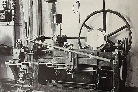
Janvier Reducing Machine Modern history. The most modern medallic engraver was developed by a Frenchman, Victor Janvier (1851-1911), and his Janvier reducing machine became the premier die-engraving pantographs of the 20th century. The earliest instruments were merely copying lathes or cameo cutters, but the remarkable contrivance has been called a wide variety of names over the years: tour a reduire, tour a portrait, medallion engraver or lathe, portrait lathe, transfer lathe, reducing machine or lathe, diesinking machine, mechanical engraver, pantographic reducer, medal reducing lathe, medal and cameo reducing and engraving lathe, and, finally, by their maker's name (as Hill, Contamin, or the famed Janvier). The products which can be created from dies made by this method are not limited to coins, medals and cameos in all, but also anything coined. Any small object struck in a press from dies, as buttons, emblems, jewelry items, small parts and such, even tableware utensils could be coined. (It was not surprising that the tableware industry early embraced the Janvier and acquired more of these machines than any other industry.) But what was so astonishing was the mint officials of the world who had to create high quality coin dies beating a path to the door of Janvier's small Paris factory. In the early 20th century if modern mints wanted quality diecutting and the highest fidelity coin reductions they needed a Janvier engraving machine. History of the Die-engraving Pantograph Existing records of the earliest known machines which reproduce three-dimensional images were either copying machines or virtual cameo-cutting lathes. These existed in England, Europe and Russia. They could reproduce a design in metal, but nothing as hard as steel. The first true die-engraving pantographs were developed independently in France and the Low Lands. They not only had a bar affixed to a fulcrum, which provided the required reduction, but also the ability to cut into steel. These included the Hulot (no other name recorded) whose machine appeared in Belgium in 1766. This early reducing lathe was to have an influence on others who built improved pantographs in a number of countries. One of Hulot's machines still exists in a Brussells museum today as tacit testimony to this early creation. In France, Saxton Merchlein, a machinery inventor, developed his reducing machine in 1767; while contemporary with the Hulot, each was developed independent of the other. Merchlein's machine was perhaps the first to be used for engraving coin dies at a mint, the Paris Mint. Privately in France, Jean Baptiste Barthelemy Dupeyrat (1759-1834), a young mechanic, had developed a reducing lathe that attracted the attention of Matthew Boulton. Boulton obtained one of Dupeyrat's lathes in 1790 for his Soho Mint in Birmingham. Obviously national mints in both France and England became interested in these machines, leading to a second generation of improvements. However, it was the private industry in both these countries that were to do the most to advance the mechanical engraver. Engineering developments in private industry were quickly assimilated in the equipment of national mints; but the technology did not flow in the opposite direction. New ideas developed in national mints became closely guarded secrets. Advancement in the field – particularly for medals – had to come from private mechanical engineers working independently outside any national mint. Second generation machines were built by Belgium medallist Joseph Pierre Braemt (1796-1864) in 1824 (undoubtedly based on the Hulot machine of his countryman). Braemt's machine still exists in the Brussells Mint Museum. Also the Hulot machine inspired one developed by Benjamin Cheverton, a British machinist in 1826. In addition to the private Soho Mint, Dupeyrat's machines were sold to the British Royal Mint, in 1819, to the Karlsrue Mint in Germany, and other European mints about the same time. When James Watt, Boulton's partner in the Soho Mint, retired in 1804 he worked on improving the Dupeyrat lathe, continuing his endeavors until his death in 1819. In France in 1820 an ingenuous machinist Ambrose Wohlgemuth built a "medal and cameo reducing and engraving lathe." He used modern principles of reduction but still employed pedal power, as had all previous machines. His lathe still exists and is in the Conservatoire des Arts et Metier, Paris. A decade later in Beasancon France, a surgeon who took up sculpture, Jean Baptiste Maire (1787-1859) developed his own reducing machine after creating his first medals in 1834. Perhaps it was used by the Paris Mint since it is in the Conservatoire des Arts et Meitiers alongside Wohlgemuth's machine. All first and second generation reducers had a fixed cutter; the work rotated while the cutting point was fixed to the bar. This was a true lathe. Third generation reducers employed the rotating cutting point; in effect transforming the medallic pantograph into a mechanically controlled milling machine.

Wayne Homren, Editor The Numismatic Bibliomania Society is a non-profit organization promoting numismatic literature. See our web site at coinbooks.org. To submit items for publication in The E-Sylum, write to the Editor at this address: whomren@gmail.com To subscribe go to: https://my.binhost.com/lists/listinfo/esylum All Rights Reserved. NBS Home Page Contact the NBS webmaster 
|